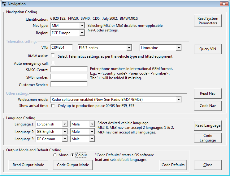

Scan the ibus and retrieve information on every connected device.View the ibus data in real time and in plain text! 90% of all ibus messages can be displayed in English.Here's what the current NavCoder window looks like (this is the new v3 version, with hugely improved user interface):ĭownload the current NavCoder Beta version It is still actively supported by the author. It has grown much over the last few years, and was last updated in December 2017, over 10 years since the initial release!. Its written in VB6, and was started in 2006. NavCoder is a Windows application to reprogram BMW navigation computers and other ibus devices. Instructions on setting up the debug environment are available in the Operation and Testing section.NavCoder Website Welcome to the NavCoder website! See latest Arduino sketch code for more details (debug comments). Use your favorite serial monitoring software – I personally prefer PuTTy. For the UNO R3 we use pins 7 (Rx) and 8 (Tx) for our Software Serial. This allows us to use a USB-TTL converter to monitor what the Arduino is seeing and doing. The Arduino programming includes optional debugging via Software Serial. Pins 14 (RESET) and 15 (SENSE) are not used for this project. We do not need this feature, so we ground pin 8 (SI), the comparator input. Pins 7 (SO) and 8 (SI) on the TH3122 can be used as a universal comparator. Pin 3 (VTR) is connected to VCC It sets reset timing (See TH3122 Datasheet). This is used in the Arduino programming to tell when it’s safe to send data onto the K-Bus. The SEN/STA signal stays High while there is data/activity on the K-Bus, and goes Low when there is noĪctivity. Pin 9 (SEN/STA) is connected to the Arduino’s digital input pin 3. Pin 10 (RX) is connected to the Arduino’s receive pin. Pin 11 (TX) is connected to the Arduino’s transmit pin. The TH3122 will automatically re-enable VCC (Pin 16) once it sees activity on the I/K-Bus – which will wake up our arduino. We will use this in the arduino programming to shut down the arduino when there is no activity on the I/K-Bus after a certain time period. Pin 2 (EN) enables the +5 Voltage regulator output on pin 16 (VCC). I stuck with 1uF for flexibility (smaller variety of parts), due to the MAX232 datasheet specifying 1uF – for the RS232 interface. VCC (Pin 16) provides the arduino with +5V It is also connected to a 1uF capacitor (C5) to reduce short time voltage drops.Ĭapacitor C5 is suggested to be above 2uF in the TH3122 datasheet. The circuit has a 47uF capacitor on the +12V line to reduce short time voltage drops. +12V supply voltage passes through a diode (D1), and connects to pin 1 (VS) which powers the TH3122. The RC filter is a 10 ohm resistor and a 100pF non-polarized capacitor. The RC filter minimizes EMI on the BUS line, and is recommended per TH3122 datasheet.

The BMW K-Bus wire passes through an RC filter and then connects to pin 6 (BUS) on TH3122.


 0 kommentar(er)
